
7. The Triangle Approximation Model
Approximating the Unrolled Shape with Triangles:
Now that the blade has been modeled in both Geometry Expressions and Maple, it is time to look at how we can change the way it is built. Like a sphere, our shape cannot be unrolled into a flat surface. However, it can be approximated with triangles. With Geometry Expressions, we can actually use the top view model to make a figure that can be cut out of a flat material and folded up to create the Twisted Savonius. The more sides we use for the approximation, the closer we get to the actual shape. We can scale these figures up and create larger and larger turbines (with stronger and stronger materials). As we do this we can also make our approximation more and more exact. Finally, we can get close (and big) enough that we can replace the triangles with one smooth shape, which can be cut out of a strong but reasonably flexible and stretchable fabric and wrapped around a simple-to-make smooth frame. This shape and method could then be utilized for anyone to easily build their own twisted Savonius wind turbine of full size at about two meters high.
To learn more about the how the triangle approximations approach a mathematical surface area limit, skip to the next chapter.
For more information on the applications of the models, and how you can build a scale model of the triangle-approximated turbine, skip to chapter 9.
To learn more about the process of building the triangle approximation models, read on below.
Making the Cutouts in Geometry Expressions:
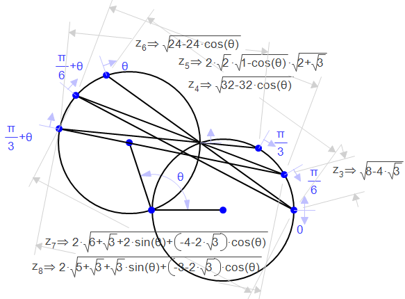
Because it is much simpler, and more geometrically accurate, a basic top view model is used to make the cutouts of the triangle approximations. First, two circles with the same radius are drawn and the angle between them (as has been discussed before) is constrained as theta. We want to have as few variables as is possible, so it is best to use whole numbers for the radii and to make one of the radii between which the angle is constrained have a slope of 0. Then, points are placed on each circle and constrained to be proportional along the circle. The first point on one circle will be at 0 and on the other it will be theta. From there, add your chosen fraction of pi to the previous constraint on each circle until you reach pi and pi+theta. The smaller the fraction of pi, the more sides your approximation will have. Next, draw line segments from the first point on one circle to the first point on the other, the second point to the second point and so on. Finally, draw more line segments, this time from the first to the second, second to third, and so on, again on opposite circles. Now, you need to calculate the symbolic length of each of the lines you just drew. This is a very complicated process, so I recommend finding some sort of a system for keeping all of the calculations organized. This image shows the calculations for the first few pieces of a six-sided triangle approximation cutout with a circle of radius 2:
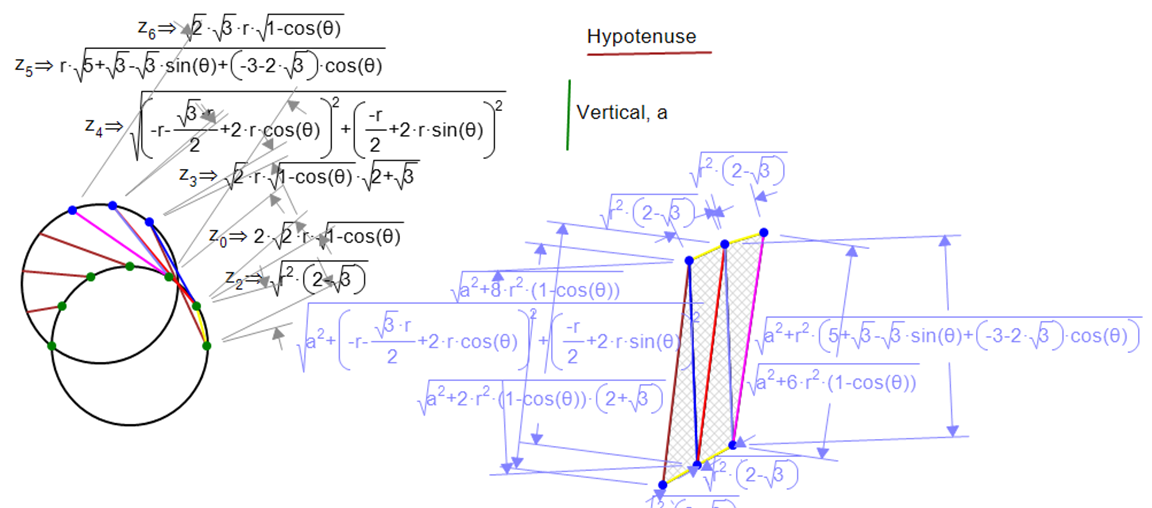
As the calculations are made, we can start to build our cutout. To make the top view model mathematically three-dimensional, the vertical constraint, height a, needs to be incorporated. The Pythagorean Theorem (a2+b2=c2) allows this to be done by squaring the Geometry Expressions calculation (representing the horizontal distance b), then adding the variable parameter a2, and then taking the square root of the total. This new equation is copied and pasted into the constraint for each corresponding line segment on the unrolled model. The model is systematically built up until the entire figure is complete. The figure below shows this process with color-coding matching the sides on the top view and unrolled models.
A video of this constrution process, sped up to 8x actual speed, for the 4-sided approximation model is below:
This construction method is applied to every triangle approximation model, with the spacing of the points on each top view circle and the number of triangles being the only differences between the construction of each model. The completed 32-sided cutout model, animated through the twist angle theta, is below. Note the changing surface area of the blade, calculated approximately and displayed below the figure.
| Previous | Next |